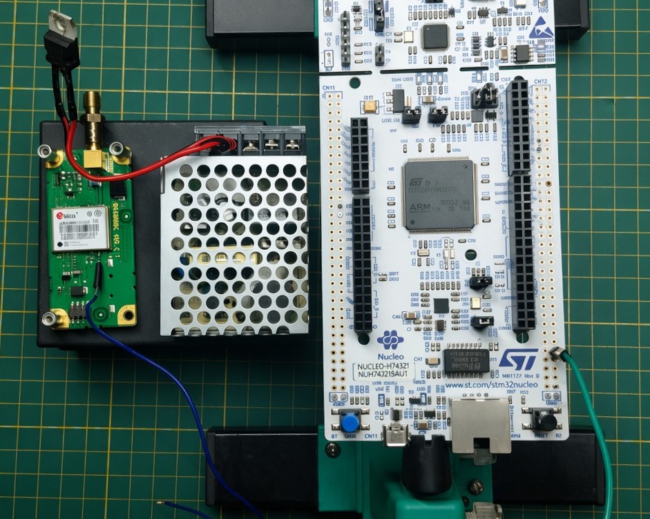
The idea
I want to build a programmable function generator for my lab.
The basic architecture is:
STM32H743ZI → high-speed DAC → analog output
with a u-blox GNSS receiver providing a long-term timing reference.
The first target is relatively simple: generate a clean sine wave up to at least 10 MHz. The exact output stage and reconstruction filter still need to be designed.
I chose the STM32H743ZI for a very practical reason: I already have a NUCLEO-H743ZI board sitting on my bench.
What I want it to do
The generator should eventually be useful for several different tasks:
- conventional function-generator work;
- automated measurements;
- arbitrary waveform generation;
- signal playback from recorded samples;
- synchronization experiments;
- SDR experiments.
The Python interface is an important part of the design.
For example, together with my programmable Hantek DSO2D10, the generator could automate measurements such as frequency-response sweeps:
                 Python
                /      \
               ▼        ▼
          Generator    DSO2D10
               │          │
               └─── DUT ──┘
                    │
                    ▼
                  NumPy
Instead of manually changing the frequency and reading the oscilloscope, a script could perform the sweep and calculate the amplitude and phase response.
GNSS timing
I also want to experiment with using a u-blox LEA-M8T as a timing reference — but not as the thing that directly clocks the DAC.
Initially I was planning to have the GNSS timepulse discipline a local high-frequency oscillator in a closed loop. In practice, that’s a much harder problem than it sounds: building a clean, low-jitter disciplined oscillator is a project on its own, and getting it wrong would inject more noise into the signal chain than it removes.
So the plan changed. The DAC clock is now generated locally, on the STM32 itself:
4 MHz reference → STM32 clock multiplication → 100 MHz square wave → DAC clock input
GNSS still has a role, just a smaller one: instead of actively disciplining the clock in real time, the PPS output is used to check the local clock’s long-term accuracy — measure the drift, log it, and know how far off the free-running STM32 clock actually is over minutes or hours.
         LEA-M8T
      ┌───────────┐
 PPS ─┤           │
      └─────┬─────┘
            │
            ▼
    ┌────────────────┐
    │   STM32H743    │
    │                │
    │ Timer capture  │
    │ (drift check)  │
    └────────────────┘

    4 MHz ref ──▶ STM32 clock mult. ──▶ 100 MHz ──▶ AD9744 clock in
This is a much simpler architecture than an actively disciplined oscillator, and it’s a more honest starting point: get a stable, known-drift clock working first, and only reach for real discipline later if the accuracy turns out not to be good enough.
Power supply
The GNSS receiver will be powered from a Mean Well RS-15-5 AC/DC supply.
Rather than feeding the receiver directly from the 5 V switching supply, I plan to use a 3.3 V LDO between the supply and the LEA-M8T.
       AC mains
           │
           ▼
    ┌─────────────┐
    │ Mean Well   │
    │   RS-15-5   │
    └──────┬──────┘
           │ 5 V
           ▼
    ┌─────────────┐
    │   3.3 V LDO │
    └──────┬──────┘
           │
           ▼
        LEA-M8T
The LDO provides a clean local supply for the GNSS receiver and adds another stage of filtering and regulation between the switching supply and the timing hardware.
The LEA-M8T also has its own internal power regulation, so the external LDO is an additional stage rather than the only regulator in the receiver’s power path.
The Mean Well’s protective earth is treated separately from the signal ground. The PE connection is bonded to the metal enclosure and the protective earth conductor, while the GNSS V− is used as the DC return.
The final PCB will also have local decoupling and filtering for the GNSS receiver, STM32 and DAC. The exact grounding and power-distribution scheme will be determined during the hardware design.
Arbitrary waveforms
Another reason for building the generator is to have direct control over the samples.
A waveform generated in Python could be transferred to the STM32 and reproduced through the DAC.
That means the instrument could generate much more than a sine wave:
Python
   │
   ▼
sample table
   │
   ▼
STM32 + DMA
   │
   ▼
  DAC
   │
   ▼
analog signal
Recorded signals could potentially be replayed in the same way, making the generator useful as a repeatable signal source for testing filters, amplifiers, SDR chains and other hardware.
The DAC
The main component I need to investigate now is the DAC.
The initial requirement is:
10 MHz sine output
One candidate is the AD9744, a 14-bit, 210 MSPS current-output DAC.
| Parameter | AD9744 |
|---|---|
| Resolution | 14 bit |
| Maximum update rate | 210 MSPS |
| Target output frequency | ≥ 10 MHz |
| Interface | CMOS |
| Output | Differential current |
| Reference | Internal 1.2 V |
| Supply | 3.3 V |
| STM32 interface | Potentially suitable |
| Arbitrary waveform | Suitable |
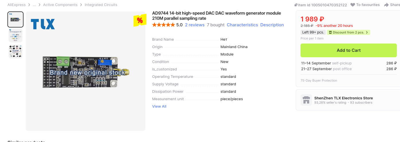
The important part is that the DAC itself is only one piece of the signal chain. Clock quality, sample rate, reconstruction filtering, current-to-voltage conversion and PCB layout will ultimately determine how clean the 10 MHz output actually is.
A 100 MHz sample clock is one possible starting point: at a 10 MHz output frequency this gives ten DAC updates per cycle, while lower output frequencies naturally get more samples per period.
The final clock frequency is still to be determined.
Clocking architecture
The clocking architecture ended up simpler than I originally planned.
Rather than building a disciplined local oscillator, the STM32 itself generates the DAC clock: a 4 MHz reference is multiplied up to 100 MHz internally and fed out as a square wave directly into the AD9744’s clock input. GNSS PPS is used separately, purely to measure how much the STM32 clock drifts over time — not to correct it in real time.
Conceptually:
   4 MHz ref
       │
       ▼
┌─────────────┐
│  STM32H743  │
│ clock mult. │
└──────┬──────┘
       │  100 MHz square wave
       ▼
┌───────────────┐
│    AD9744     │
│      DAC      │
└───────┬───────┘
        │
        ▼
    analog OUT

         GNSS PPS
             │
             ▼
     ┌───────────────┐
     │   STM32H743   │
     │ drift logging │
     └───────────────┘
This trades some long-term accuracy for a much simpler and more predictable clock path. If the drift turns out to matter for a given application, an actively disciplined oscillator is still an option later — but it’s not a prerequisite for getting the first prototype working.
Next
- work out the STM32 → DAC interface;
- implement the 4 MHz → 100 MHz clock multiplication on the STM32;
- investigate the LEA-M8T PPS output for drift logging;
- determine the required DAC clock frequency and jitter budget;
- design the DAC output stage and reconstruction filter;
- build the first DAC prototype;
- connect it to the Hantek DSO2D10 and start automating measurements.
For now, this is just the beginning.
STM32 + DAC + GNSS-checked clock + Python → a programmable signal source for the lab.